Nugroho's blog.

Saturday, April 4, 2015

Arduino Pro Mini (ATMega 328 Based), my New Toy

I saw it at electronic part shop while shopping for my DIY guitar preamp part. It based in ATMega 328 and it waking up my years-sleeping microcontroller spirit :D

I always love assembly language, I have several project on ATMega based microcontroller as programmer but it's just that. I just love programming without bothered by hardware, minsys or whatnot.

It's true that arduino language is not asm; it's simplified C. But it come in package, I just have to program it and it'll work. It's the closest thing I got to hardware related interface, for now (I still have a plan that some day I'll master both microcontroller hardware and software interfacing :) )

Anyway, I bought this Arduino Pro Mini and an USB to TTL module.


It just my luck that I bought that PL2303HX module and not Sparkfun breakout board or FTDI connector as my Arduino Pro Mini  layout is totally different; it has same dimension as original but the hole for pins is different (it has more hole than the original). The breakout board probably won't match and maybe useless (I don't konw about FTDI). So I think the pl2303hx usb to ttl usb-stc-isp is my best shot.

My luck, or probably not, it means my Arduino Pro mini is the clone, :)

I download Arduino IDE for my MacBook Air with OS X Yosemite. 

Install it, there's no problem as I changed my macbook setting on software installer permission (set to ANY)

Ran the IDE, use the example code, blinking LED.

compile it, OK

Upload it, this error message appear:

Arduino: 1.6.2 (Mac OS X), Board: "Arduino Pro or Pro Mini, ATmega328 (5V, 16 MHz)"

Sketch uses 1,068 bytes (3%) of program storage space. Maximum is 30,720 bytes.

Global variables use 11 bytes (0%) of dynamic memory, leaving 2,037 bytes for local variables. Maximum is 2,048 bytes.

avrdude: stk500_recv(): programmer is not responding
avrdude: stk500_getsync() attempt 1 of 10: not in sync: resp=0x00
avrdude: stk500_recv(): programmer is not responding
avrdude: stk500_getsync() attempt 2 of 10: not in sync: resp=0x00
avrdude: stk500_recv(): programmer is not responding
avrdude: stk500_getsync() attempt 3 of 10: not in sync: resp=0x00
avrdude: stk500_recv(): programmer is not responding
avrdude: stk500_getsync() attempt 4 of 10: not in sync: resp=0x00
avrdude: stk500_recv(): programmer is not responding
avrdude: stk500_getsync() attempt 5 of 10: not in sync: resp=0x00
avrdude: stk500_recv(): programmer is not responding
avrdude: stk500_getsync() attempt 6 of 10: not in sync: resp=0x00
avrdude: stk500_recv(): programmer is not responding
avrdude: stk500_getsync() attempt 7 of 10: not in sync: resp=0x00
avrdude: stk500_getsync() attempt 8 of 10: not in sync: resp=0x00
avrdude: stk500_recv(): programmer is not responding
avrdude: stk500_getsync() attempt 9 of 10: not in sync: resp=0x00
avrdude: stk500_recv(): programmer is not responding
avrdude: stk500_getsync() attempt 10 of 10: not in sync: resp=0x00
Problem uploading to board.  See http://www.arduino.cc/en/Guide/Troubleshooting#upload for suggestions.

  This report would have more information with
  "Show verbose output during compilation"
  enabled in File > Preferences.


Install FTDI drivers, not work, obviously because I don't use it.8

try it in my Linux Debian machine (after install it via sudo apt-get install arduino command), success

back to mac, success too, strange

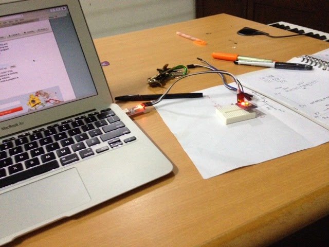
After several success and error upload, it turned out that my tx rx connection is not thigh enough, heheh...

The pictures below made after I secure the connection by permanently solder it. Not my actual plan because initially I prefer it in plug and play form.

Some note

Make sure that PL2303HX and Arduino have this connection right
Vcc to 5V
GND to GND
TX to RX
RX to TX

Before clicking upload button on IDE, we have to press and hold reset button on Arduino board and release about one second after it (or after console displaying message: 'sketch size...').


I've found new kind of error like this

Arduino: 1.6.2 (Mac OS X), Board: "Arduino Pro or Pro Mini, ATmega328 (5V, 16 MHz)"

Sketch uses 4,480 bytes (14%) of program storage space. Maximum is 30,720 bytes.
Global variables use 216 bytes (10%) of dynamic memory, leaving 1,832 bytes for local variables. Maximum is 2,048 bytes.
avrdude: ser_open(): can't open device "/dev/cu.usbserial": Resource busy
ioctl("TIOCMGET"): Inappropriate ioctl for device
Problem uploading to board.  See http://www.arduino.cc/en/Guide/Troubleshooting#upload for suggestions.

  This report would have more information with
  "Show verbose output during compilation"
  enabled in File > Preferences.

It happened when I open serial monitor using Terminal apps on OS X and trying to upload the sketch while it running command

$ screen /dev/cu.usbserial

or 

$screen /dev/cu.HC-05-DevB

We have to close it first (not just detach) using command

$<ctrl>-a-\

and all is well, :)

Thursday, April 2, 2015

DIY Guitar PreAmp (or Distortion StompBox) using TL 074

My string acoustic-electric guitar is borrowed and not back, leave my classic nylon string Yamaha guitar and an Ibanez clone with is by itself stand at the opposite pole of my need (rock/metal amplified sound or warm natural classic).

I need something between that and decide to install piezo on my classic nylon string. It pretty straightforward, just need few minutes. The problem is when i plugged it on my amp, it has almost no sound. I have to crank the volume knob all the way up to hear 'normal' level volume. It need pre-amplifier.


I uninstalled the piezzo (what I'm thinking at that moment, :D ) and using my Ibanez clone as testing guitar, with normal jack and all.

here the schematic


It Occured to me that this Pre-Amp could act as Distortion effect if we set the gain super high. I do it by add a resistor parallel to 100k. And the sound is suddenly very different. It's very clipped and distorted yet there's something missing (for me). I like soft clipping. So I plan to tinkering with some resistor value or add potentiometer to it


If we don't want distortion, just louder gain, we could always using two stage preamp (I don't know the proper name of it)


Thursday, March 26, 2015

Modifikasi Flasher Lampu Sein LED


Seminggu ini berusaha me-LED-kan semua lampu (kecuali lampu utama). Berguna untuk meringankan kerja aki dan alternator, :)

Seperti biasa, tak sulit, hanya tinggal ‘plug-n-play’. Lampu rem, lampu senja, semua jadi memiliki watt yang kecil.

(saya lihat spek dari lampu stock-nya adalah 24 watt untuk satu lampu rem saja, waduh berarti satu lampu menghabiskan dua ampere!)

Seperti biasa juga, ada masalah. Kedipan lampu sein jadi lebih cepat karena flasher dirancang untuk dialiri arus yang besar. Flasher memang dirancang sedemikian sehingga jika ada lampu sein yang putus maka kedipan akan lebih cepat (karena arus yang mengalir lebih kecil) untuk memperingatkan kita agar segera mengganti dengan lampu baru.


Tapi LED kan tahan lama bertahun-tahun.

Saya juga tak begitu memerlukan “fitur peringatan dini” bahwa lampu sein saya putus. Yeah, tak ada peringatan dini untuk lampu rem atau lampu senja putus kan? Kita harus selalu mengecek mereka secara manual.

Nah, fitur ini di-disable saja.

Paling mudah dengan menambahkan resistor 6 Ohm yang dipasang secara paralel dengan LED. Dengan demikian arus yang mengalir akan tetap 2 Ampere (LED hanya membutuhkan beberapa miliampere) dan flasher tetap bekerja normal, kedipan lampu sein juga normal, namun plastik batok lampu kita akan bisa leleh karena resistor melepaskan banyak panas. (yeah, cara tersebut memang mudah, lampu sein akan menyala terang karena menggunakan LED, namun arus yang mengalir akan tetap, tidak ada penghematan energi dari aki)

Yang efektif adalah dengan mengotak-atik Flashernya.

Caranya,…, DuckDuckGoing,…, dan waduh…

Banyak sekali caranya, tergantung jenis flashernya.

Secara umum, fitur untuk deteksi lampu mati terbuat dari resistor yang berbentuk kawat lengkung.

Jika flasher kita seperti ini, tinggal diamplas saja kawat lengkungnya sedikit, pasang lagi, cek, jika kedipan kurang lambat, amplas lagi, cek lagi, … dst.

Jika tidak ada resistor berbentuk kawat maka cari resistor bernama R1 kemudian ganti dengan resistor bernilai 1M Ohm. Jika Flashernya menggunaka IC, potong sambungan di kaki IC nomor 7, …. (dan banyak lagi hasil DuckDuckGo yang lain)

Saya punya dua flasher, dengan nomor kode komponen yang sama, 81980-22070, namun ketika saya buka ternyata sangat beda sekali. Satu memiliki Resistor lengkung (yeah…) dan satunya hanya terdiri dari rangkaian resistor, dioda, kapasitor dan transistor.

Cara paling mudah sebenarnya adalah dengan mengamplas Flasher saya yang punya resistor model kawat. Namun cara demikian kurang cocok bagi saya karena jika suatu saat saya ingin mengganti lagi LED dengan lampu stock maka kedipan akan jadi sangat lama atau malah tidak berkedip sama sekali.

Akhirnya saya otak-atik flasher kedua. Ganti R1 dengan resistor 1M Ohm dan,…., gagal…

Ada forum lain yang mengatakan R2 yang diganti, ok, coba lagi dan gagal, ….

Penasaran, saya balik PCB-nya, urut rangkaiannya

Tidak sulit karena tidak ada IC-nya, ini hanya semacam timer sederhana. Timer semacam ini waktunya ditentukan oleh kapasitor dan resistor yang terhubung seri sehingga saya hanya perlu cari resistor yang seperti itu dan ternyata ketemu dua yang semacam itu!

Yang satu pastilah untuk kedipan normal, yang satu untuk kedipan cepat, disable saja untuk yang kedipan cepat, yaitu yang terangkai seri dengan kapasitor yang bernilai kecil

(dalam hal ini ternyata resistor dengan label R5 yang harus saya copot, bisa disambung dengan resistor 1M Ohm atau dibiarkan copot saja)


Tes, ganti semua lampu sein kanan dengan LED, waktu kedipan ternyata sama dengan yang kiri. OK, ganti semuanya dengan LED, :)


(lampu sein = sen = reting = riting = liting, tergantung kebiasaan menyebut di masing-masing daerah, :)  )


Modified LED Turn Signal Light Flasher

This week I tried to light all the lights (except the main lights). Useful to ease the work of batteries and alternators, :)

As usual, it's not difficult, just stay 'plug-n-play'. Brake lights, dusk lights, all have a small wattage.

(I see the spec from the stock light is 24 watts for just one brake light, it means that one lamp consumes two amperes!)

As always, there is a problem. Turn on the turn signal is faster because the flasher is designed to flow large currents. Flasher is designed so that if there is a broken turn signal, the flicker will be faster (due to smaller flowing currents) to warn us to immediately replace it with a new lamp.

But LEDs last a long time.

I also don't really need the "early warning feature" that my turn signal breaks. Yeah, there's no early warning for the brake lights or the dusk lights right? We must always check them manually.

Well, this feature is disabled only.

It's easiest to add a 6 Ohm resistor installed in parallel with the LED. Thus the current flowing will remain 2 Ampere (LEDs only need a few milliamperes) and the flasher will still work normally, the flashing of the turn signal is also normal, but our light shell plastic will melt because the resistor releases a lot of heat. (yeah, this method is easy, the turn signal lights up brightly because it uses LEDs, but the current flowing will remain, there is no energy savings from the battery)

What is effective is by tinkering with the Flasher.

The trick, ..., DuckDuckGoing, ..., and oh my ...

There are lots of ways, depending on the type of flasher.

In general, the feature for detection of dead lights is made of resistors in the form of curved wire.

If our flasher is like this, just sand the curved wire a little, plug it in again, check, if it blinks slowly, sandpaper again, check again, etc.

If there is no wire-shaped resistor, look for a resistor named R1 then replace it with a resistor worth 1M Ohm. If the Flasher uses IC, cut the connection at the foot of IC number 7, ... (and many other DuckDuckGo results)

I have two flasher, with the same component code number, 81980-22070, but when I open it it is very different. One has a curved resistor (yeah ...) and the other only consists of a series of resistors, diodes, capacitors and transistors.

The easiest way is actually to sand my Flasher which has a wire model resistor. However, this method is not suitable for me because if one day I want to replace the LED with the stock lights, the flashing will be very long or not even blink at all.

Finally I tweaked the second flasher. Replace R1 with a 1M Ohm resistor and, ..., fail ...

There is another forum that says R2 is replaced, ok, try again and fail, ...

Intrigued, I flipped to look the back of the circuit board, manually routing the sequence with my finger.

It's not difficult because there's no IC, it's just a simple timer. This kind of timer is determined by a series of capacitors and resistors so I only need to find a resistor like that and it turns out that I found two of them!

One must be for normal blinking, one for fast blinking, just disable it for the fast blinking, which is coupled with a series of small-value capacitors

(in this case it turns out that the resistor with the R5 label that I have to dislodge, can be connected with a 1M Ohm resistor or just left  it open/disconnected)


Test, replace all the right turn signal with the LED, the flashing time is the same as the left one. OK, replace everything with LED, done, :)


Monday, February 16, 2015

Scripting in SwishMax

The movies below's result of my tinkering with SwishMax this morning; consist of me abusing the script to force the project done in just one frame, :)

Moving a Box using Script on SwishMax


Move a Box by a Click of Button on SwishMax


Increasing the Width of a Box using Script on SwishMax


Toggling the Move Direction of a Box using Script on SwishMax


Control the Speed (using Text Input) of a Box Moved by Script on SwishMax

Tuesday, December 30, 2014

Gnome 3 on Freebsd (self documentation)

install it using

#pkg install gnome3

/etc/fstab 

proc           /proc       procfs  rw  0   0

/etc/rc.conf

gdm_enable=“YES”
gnome_enable="YES"

The menu is missing

install Parallel Tools

#cd /usr/ports/emulators/parallels-tools/ && make install clean

but it need kernel source. 

Install via svn

#pkg install devel/subversion

# svnlite checkout http://svn0.eu.freebsd.org/base/releng/10.0/ /usr/src

run it again

#cd /usr/ports/emulators/parallels-tools/ && make install clean


Playing with FreeBSD


Got boot-only iso and managed to install it on my Parallel Desktop on my Macbook Air with Yosemite. 

Of course it just CLI.

Strange, the root shell have tab completion feature, but the normal users didn’t.

(DuckDuckGo-ing)

The answer come from 2003 and 2005 Mailing-List, :)

To enable tab completion
 
$chsh -s /bin/tcsh
 
(it didn’t enable tab completion actually , it change shell with tab completion feature :) )
We could so use
 

$chsh -s /bin/csh 

 
tcsh shell support tab completion too.

 
Another thing is, normal user can’t use sudo command (because it’s not installed, :P )
So,  install sudo first (I used pkg command instead of pkg_add)
 
#pkg install sudo 
 
 
edit /usr/local/etc/sudoers as root and visudo command (don’t edit it using regular vi editor, or ANY editor)

%visudo

add this

username ALL=(ALL) ALL

 
and life become more easier...


Monday, December 22, 2014

Compare Native Loop Time in Python with "homemade" Fortran Module

This code print d and e as result of two matrix addition, e's using python native code, d's using fortran module compiled with F2PY

The code
import numpy as np
import aravir as ar
import time

n = 1000

u = np.ones((n,n))
v = np.ones((n,n))
e = np.ones((n,n))

t = time.clock()
d = ar.add3(u,v)
tfortran= time.clock()-t

t = time.clock()
for i in range (n):
for j in range (n):
e[i,j] = u[i,j]+v[i,j]
tnative = time.clock()-t

print 'fortran ', d
print 'native', e
print 'tfortran = ', tfortran, ', tnative = ', tnative


The fortran module I imported to python
        subroutine add3(a, b, c, n)
double precision a(n,n)
double precision b(n,n)
double precision c(n,n)

integer n
cf2py intent(in) :: a,b
cf2py intent(out) :: c,d
cf2py intent(hide) :: n
do 1700 i=1, n
do 1600 j=1, n
c(i,j) = a(i,j)
$ +b(i,j)

1600 continue
1700 continue
end

save it as aravir.f and compile using
$ f2py -c aravir.f -m aravir

And here the result
$ python cobamodul.py 
fortran [[ 2. 2. 2. ..., 2. 2. 2.]
[ 2. 2. 2. ..., 2. 2. 2.]
[ 2. 2. 2. ..., 2. 2. 2.]
...,
[ 2. 2. 2. ..., 2. 2. 2.]
[ 2. 2. 2. ..., 2. 2. 2.]
[ 2. 2. 2. ..., 2. 2. 2.]]
native [[ 2. 2. 2. ..., 2. 2. 2.]
[ 2. 2. 2. ..., 2. 2. 2.]
[ 2. 2. 2. ..., 2. 2. 2.]
...,
[ 2. 2. 2. ..., 2. 2. 2.]
[ 2. 2. 2. ..., 2. 2. 2.]
[ 2. 2. 2. ..., 2. 2. 2.]]
tfortran = 0.069974 , tnative = 1.202547

The Desktop, :)


323f (5) amp (1) android (12) apple (7) arduino (18) art (1) assembler (21) astina (4) ATTiny (23) blackberry (4) camera (3) canon (2) cerita (2) computer (106) crazyness (11) debian (1) delphi (39) diary (286) flash (8) fortran (6) freebsd (6) google apps script (8) guitar (2) HTML5 (10) IFTTT (7) Instagram (7) internet (12) iOS (5) iPad (6) iPhone (5) java (1) javascript (1) keynote (2) LaTeX (6) lazarus (1) linux (29) lion (15) mac (28) macbook air (8) macbook pro (3) macOS (1) Math (3) mathematica (1) maverick (6) mazda (4) microcontroler (35) mountain lion (2) music (37) netbook (1) nugnux (6) os x (36) php (1) Physicist (29) Picture (3) programming (189) Python (109) S2 (13) software (7) Soliloquy (125) Ubuntu (5) unix (4) Video (8) wayang (3) yosemite (3)