Menyalakan LED 3 dengan mode PWM dengan perintah analogRead, sehingga nyala LED berangsur-angsur dari redup ke terang ke redup lagi (255 tingkat kecerahan).
Menyalakan LED 2 dengan perintah melalui port serial bluetooth dari Mac OS X.
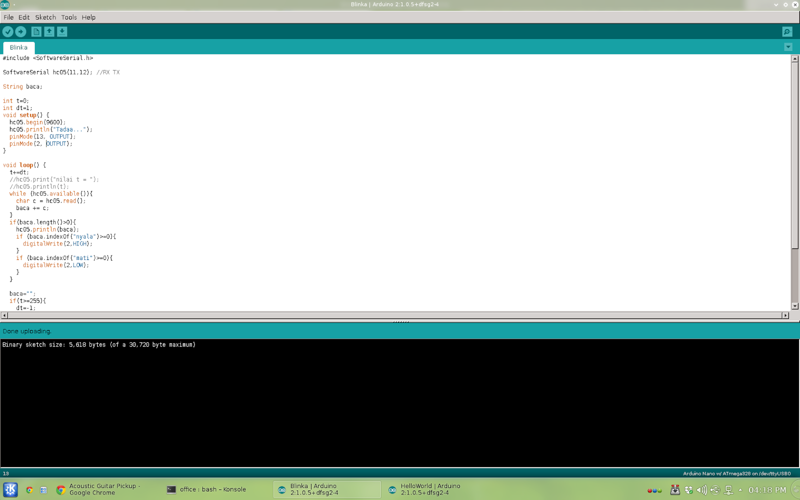
(program ditulis dan dijalankan di linux Debian)
led pin 3 dapat dinyalakan (setelah microcontroler tersambung dengan komputer via bluetooth) dengan mengetikkan 'nyala' atau 'mati' pada konsole di komputer.
#include <softwareserial .h>
SoftwareSerial hc05(11,12); //RX TX
String baca;
int t=0; int dt=1; void setup() { hc05.begin(9600); hc05.println("Tadaa..."); pinMode(13, OUTPUT); pinMode(2, OUTPUT); }
void loop() { t+=dt; //hc05.print("nilai t = "); //hc05.println(t); while (hc05.available()){ char c = hc05.read(); baca += c; } if(baca.length()>0){ hc05.println(baca); if (baca.indexOf("nyala")>=0){ digitalWrite(2,HIGH); } if (baca.indexOf("mati")>=0){ digitalWrite(2,LOW); } }
We could write code in it, connecting parts on breadboard (or project-board), auto-route it to schematic and pcb layout (single or double layer).
It has several arduino board ready on parts section
Dengan Fritzing, kita bisa menulis kode mikrocontroler di sini, memasang komponen dan menyambung dengan kabel di project-board, kemudian me-route secara otomatis menjadi skematik seperti di EWB (Electronic Work Bench), routing otomahis juga dilakukan untuk menghasilkan layout PCB seperti di Protel (mendukung single dan double-layer)
Well, not for all, but for me it becomes problem while turning led on using analogWrite command, some led just won’t completely shut down.
(Maybe it completely unrelated, but my analog reading on A0 is oscillating, very unstable)
I have the commands packed on a function
unsigned long t0 = 0;
const long dt = 1000;
void blinkNoD(int pin) {
  unsigned long t = millis();
  if(t - t0 >= dt) {
    t0 = t;
    led=!led;
    digitalWrite(pin, led);
  }
}
Since I already have delay in loop, and it really messed with the timing (not mention that maybe the analog reading instability have anything to do with it), I decided to modify the blink code, still without delay command.
KProgram ini digunakan untuk melihat nilai sensor (berupa tegangan) di port analog 0 (A0) di ATMega328.
Di sini sensor diwakili oleh potensiometer yang kaki tepinya masing-masing dihubungkan ke vcc dan ground, kaki tengah dihubungkan ke port analog 0.
Microcontroler membaca port analog 0 yang nilainya kemudian dikirimkan secara serial via bluetooth, juga untuk menyalakan empat led sesuai dengan nilai pembacaan sensor.
Karena ATMega328 memliliki resolusi pembacaan analog sebesar 10-bit, maka led diset sedemikian sehingga led 1 menyala jika nilai kurang dari 255, led 1 dan 2 menyala jika nilai sensor antara 255 dan 512, dst.
Sebagai tambahan, perintah yang digunakan untuk menyalakan led adalah analogWrite() bukan digitalWrite() sehingga meski nilai sensor kurang dari 255, kita masih bisa membedakan levelnya dengan tingkat redup-terangnya led pertama (0 mati, 50 redup, 255 nyala terang).
I also use it to blink led without delay, fade without delay, write to serial via Bluetooth module (HC-05) AND USB-to-TTL.
Notice that I have two TX and two RX, the default pin (0 and 1) for usb communication (upload sketch and debugging), the software serial TX,RX (pin 8 and 7) is used for bluetooth communication.
Here the code. I use some function to isolate some group of commands for easy debugging.
#include <softwareserial .h>
SoftwareSerial mySerial(8, 7); // RX, TX
int led = LOW; int dterang = 5; int terang = 11; unsigned long t0 = 0; const long dt = 1000;
Got HC05 Bluetooth Module last Saturday at electronic store, connect it with my Arduino Pro Mini (ATMega 328 based) the usual way: tx—rx, rx—tx, vcc—5v and ground—0v. Powered it on alongside the Pro Mini. The led indicator blinked, good sign, :)
Pairing with my Mac is easy, but make sure the pairing code is 1234, mac use 0000 as default code. If paired successfully the led blink pattern will change.
Open the serial monitor and, nothing appeared, :(
Maybe the IDE busy so I open the OS X terminal and access using screen:
$screen /dev/cu.HC-05-DevB
Still nothing happened.
Unplug all the cable, plug it again. And yup, there’s serial output (using Arduino IDE serial monitor or screen command on terminal )
I have a Mac with Yosemite.
Apparently, most of my problem with arduino board is loose cable connection, :)